
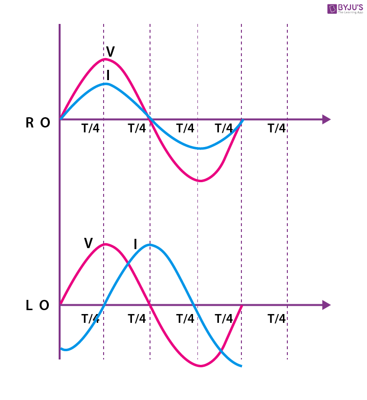
As we delve into the world of electrical circuits, it’s not uncommon to come across terms like capacitive reactance. While it may seem like a rare concept, understanding these key phrases is essential. Without needing any physics or engineering background, you can grasp the fundamental idea behind capacitive reactance.
Capacitive Reactance
When dealing with alternating current (AC) in a circuit containing a capacitor, we need to assess how this current flows. Capacitive reactance is the “resistance” that a capacitor presents to the flow of AC currents. It’s distinct from electrical resistance related to conductors, which either facilitate or impede current flow.
Capacitive reactance (Xc) measures the impedance that a capacitor opposes when an alternating voltage is applied across its terminals. This measurement is expressed in ohms and is inversely proportional to frequency.
The Relationship Between Frequency and Capacitive Reactance
It’s essential to recognize that capacitive reactance decreases as the frequency of the AC current increases. In other words, if you increase the frequency, the capacitor’s opposition to the current decreases, leading to a lower overall impedance in the circuit.
For instance, consider a 10 μF capacitor connected across a 1 kΩ resistor with an AC source at 60 Hz and another at 120 Hz. At 60 Hz, the capacitive reactance will be higher than at 120 Hz, resulting in a lower total resistance. This is why you might need to adjust your circuit configuration or component values when dealing with different frequencies.
Capacitor Configuration
Another crucial aspect of understanding capacitive reactance is knowing how different capacitor configurations can affect its value. The three primary types of capacitors are:
- Fixed Capacitors: These have a fixed capacitance value, which cannot be changed once it’s installed.
- Variable Capacitors: These allow for changes in capacitance to be made by adjusting some component or mechanism within the capacitor.
- Capacitor Networks: A group of capacitors connected together can exhibit combined reactance properties.
Inductive Reactance
When discussing capacitive reactance, we’re observing the effects of varying currents on conductors, specifically not in the presence of a capacitor but a coil (or bobbin). The concept of inductive reactance applies to all electrical coils or windings, regardless of whether they’re part of an actual device. These characteristics include:
- Number of turns
- Cross-sectional diameter
- Ratio between diameter and length
- Coil type
These parameters determine the coil’s inductance (L), measured in Henrys.
The Importance of Coil Characteristics
Understanding how different coil characteristics impact inductive reactance is crucial for designing efficient circuits. Some key considerations include:
- Number of turns: The more turns a coil has, the higher its inductance and the greater its opposition to AC current flow.
- Cross-sectional diameter: A larger cross-sectional area increases the resistance to the magnetic field generated by the current flowing through the coil.
- Ratio between diameter and length: This ratio affects the overall inductance of the coil, with longer coils typically having higher inductance.
The Role of Inductors in AC Circuits
Inductors are an essential component in many electrical circuits. They can store magnetic energy when current flows through them, opposing changes in voltage and current over time. In AC circuits, this opposition is what gives rise to inductive reactance.
In addition to their role in AC circuits, inductors also play a crucial part in DC circuits as filters or regulators, converting or regulating the supply current from DC to AC. They’re widely used in applications like motor drives, power supplies, and audio equipment.
Understanding Inductive Reactance
Inductive reactance (XL) is a measure of how much an inductor resists changes in voltage when an alternating current flows through it. The relationship between frequency and inductive reactance is the same as that for capacitive reactance: as frequency increases, the inductance decreases.
The Term “Resistance” Clarified
In discussions involving capacitive reactance and inductive reactance, the term “resistance” is sometimes used. To avoid confusion with electrical resistance related to conductors, this concept is referred to as inductive reactance (XL). It increases with increasing frequency of current flow through the coil.
Reactive Impedance
If we expand our scope beyond simple capacitive or inductive circuits, we find that reactive impedance is an important consideration. Reactive impedance accounts for differences between voltage and current in a circuit and arises from the presence of both capacitance and inductance. It’s expressed as a complex quantity on the imaginary axis.
Understanding the Role of Reactance
Reactive impedance plays a key role in AC circuits, especially when the circuit contains components with high reactance values. In cases where capacitive or inductive reactance dominate, the overall impedance changes significantly, influencing the behavior of devices within the circuit.
The Significance of Reactance Units
Reactance is expressed in ohms, an easily recognizable unit used for measuring resistance and reactance. It’s essential to recognize that while reactance and resistance share this measurement, they operate on different principles.
Distinguishing Reactance from Resistance
While both concepts are measured in the same unit, it’s crucial to differentiate between capacitive reactance and electrical resistance. Capacitive reactance is responsible for the opposition to AC currents by capacitors in a circuit, whereas electrical resistance accounts for the opposition to DC current flow through conductors.
Circuit Design Applications
Understanding capacitive and inductive reactance is essential for designing efficient circuits. Some key applications include:
- Filter design: In filter designs, high reactance values are often desired, such as in resonant filters or band-pass filters.
- Impedance matching: In impedance matching, capacitors and inductors can be used to match the impedance of different components, ensuring efficient energy transfer.
In summary, understanding capacitive and inductive reactance requires recognizing that these concepts are distinct from one another but both crucial for comprehending the behavior of electronic components in different contexts.


